Nvr Switch Wiring Diagram

Nvr switch wiring diagram. Wiring nvr switch i have just bought an nvr switch unit from axminster power tool centre for my myford but theres no wiring diagram. The 4 core is comprised brown, blue, black and earth. The start button energizes the motor and a magnetic latch in the switch mechanism. Connection 1 to 4 and 15 must be intact.
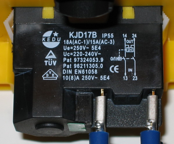
Grey blue black & blue ensure connectors are p u s hed f ly on twi c and capacitor terminals. Kjd17's fail, springs break, contacts weld, this method of estop will not stop the machine in event of a switch failure. In the above diagram even if the estop is triggered, the green button will still operate the machine while pressed (a kind of jog mode). No volt release switches alpine push button switches bulgin push button switches green buttons arcolectric push button switches.
So a standard plug on the end of the flex from the nvr switch is fine. Basic wiring diagram for machine power supplies this configuration has the following features and shows a basic setup. The cameras that i configured before show a yellow triangle alert. For situations where home runs from each camera back to the poe ports on the the poe nvr isn’t ideal, you can use a poe switch to reduce your cabling or to allow you cameras to be connected at greater distances than 750 (our admiral line has extended transmission poe) or 300 feet (normal poe nvr distances).
This cctv wiring diagram shows a single ip camera (or multiple) set up wirelessly away from the recorder (nvr) and the router. By reita feb 14, 2022 cc camera hindi, cc camera wiring diagram,. It can range from 500 meter and up to 10 km if the connection is properly established. The diagram applies to nvr switch insulated versions.
Diagram of cctv installations wiring diagram for cctv. Reviewed in the united kingdom on 5 august 2019 i was refurbishing my old lathe and was looking for a new switch. It was not supplied with box or wiring diagram but i managed to modify a standard surface mount box and work out the wiring from a small diagram of the switch. Poe ip camera wiring diagram by using cat5 cable, cat6 cable and rj 45 connector.
Usb and mouse can be connected to the usb port on nvr. Next you plug your nvr into an open port on your router. The diagram provided shows them connected, but im not sire where. A wiring diagram is an easy visual representation of the physical links and also physical layout of an electric system or circuit.
Ip camera wiring diagram download. If in any doubt consult. The relays will need to have 12 to the switch terminal and the output terminal go to the motor. The diagram applies to nvr switch insulated versions.
I have wired the earth, live and neutral to their positions but i have no idea what to do with the black The logic is the same, the camera gets plugged in at the poe port of the nvr and it will transmit data and power from the same cable. This is now how all 4 cameras show. An nvr switch stands for no voltage release.
The wiring for the live and neutral appears straight forward, but im less clear on what to do with the earth. The message is unable to connect to the network. At times the cables will cross. Connection 96 to 2 must be intact.
Using a poe switch also allows you to connect multiple cameras. But the new motor wiring diagram only shows live, neutral and earth. First you will run a cat5 cable (shown in red) from each of your cameras to a port on the poe switch. On/off n/c switch between 2 &1 must be closed.
Grey blue black & blue ensure connectors are p u s hed f ly on twi c and capacitor terminals. Complete cctv cameras wiring diagram with nvr. 5 pin ignition switch wiring diagram. The distance how far you can set up the cameras depends on the wifi bridges’ capabilities.
Just realised that if the router has its own nvr switch, you are going to have to operate both nvr switches to use the router each time. Video intended as a guide only. Usb and mouse can be connected to the usb port on nvr. Then connect your poe switch to an open port on your router.
Motors have thermo type protection switch. In this wiring connection, no need to power up the camera with extra dc supply source as single cat5 or cat6e cable can be used to provide the power to the cameras and transmit the video signals from camera to the nvr as it is an. From the 240 plug, its 3 core up to the nvr switch, then from the switch its 4 core tonthe original motor. Additionally, connect audio, video and power cables to the camera as well as nvr slots as shown in wiring diagram.
Then i unplugged the switch and the cameras and placed them in the locations they were intended to be in and powered up the poe switch and rebooted the router and the nvr. The following wiring diagram shows that how to connect a poe ip ptz camera to the nvr and joystick ptz controller. The garage sockets are protected by the left rcd. These instructions assume that the camera and the nvr are from.
There doesn't appear to be any points to link the the earth from the mains and from the motor. To manage and view the camera recording remotely on smartphones far away from the camera location, you will have to connect the ethernet router through rj45 cables which helps to connect to the nvr. The poe switch will supply power to the camera and act as a hub to connect them to the local network. This diagram is valid for an ip camera and nvr regardless of the brand names.
5.0 out of 5 stars works well for the price. Using poe switches to reduce cabling connect switch nvr installation guide. On/off n/o switch between 3 &4 must be closed ( this switch is bypassed by 13/14 when the coil is operated to latch 'on', and does the nvr part) connections 3 to 13 and 13 to 5 must be intact. Motors have thermo type protection switch.

Wiring an NVR Switch for router table

Nvr Poe Ip Camera Wiring Diagram

On off switch, button, Universal KJD 12 Amp NVR switch

CCTV diagram IP cameras, PoE injectors, WiFi bridges

Wiring Diagram Nvr Switch Electrical Wiring Diagram Images

Nvr Ip Camera Wiring Diagram Wiring Diagram

table drive motor identification Model Engineer

Poe Camera Wiring Diagram Wiring Diagram

NVR Switch What is this terminal? DIYnot Forums

NVR Setup Options Modems, Routers, Switches
Problem with NVR switch wiring Router Forums

NVR IP Camera Switch wiring question Networking

Wiring an NVR Switch for router table General

TheWoodHaven2 • View topic I don't want this NVR switch

How to Wire Analog and IP PTZ Camera with DVR and NVR

Problem with NVR switch wiring Router Forums

Nvr Switch Wiring Diagram

Wiring Diagram Nvr Switch Electrical Wiring Diagram Images

TheWoodHaven2 • View topic I don't want this NVR switch

NVR IP Camera Switch wiring question Networking

Nvr Ip Camera Wiring Diagram Wiring Diagram

Wiring NVR Switch Model Engineer

Nvr Switch Wiring Diagram
NVR Switch Wiring General Woodworking

replacement for Dewhurst switch Model Engineer