Differential Pressure Switch Wiring Diagram

Differential pressure switch wiring diagram. Wiring disconnect all supply circuits before wiring device. The electrical contacts of the switch will actuate depending on the switch points or setpoints. 2 static pressure takeoff tubes made from sturdy flame retardent abs, 2 meters of clear pvc tubing and 4. The cut in pressure is 3.
Watch as danfoss' own will guides you through two different ways to wire an mp. Once photohelic® switch/gage unit is securely mounted, plug wire assembly into 9 The two diagrams below explain the terms oil differential pressure and contact differential. The first component is symbol that indicate electrical component from the circuit.
38 wiring diagram images standard_60b09 farve mp 55 differential pressure switch, adjustable differential, low danfoss pressure switch wiring. The first diagram shows the function of the differential switch during start; Both have to be considered when using oil differential pressure switches. Leave port p2 open to atmosphere and connect pressure source to high pressure port p1
Air differential pressure switches with on/off output dimensions & wiring diagram packaging & duct mounting kit all components are packaged in a nice plain white box for private labelling. Rx3000 station differential pressure sensor with lcd display differential pressure sensor without lcd display A differential pressure switch is designed to sense a difference in pressure between two pressure sources in the plant for control purposes. Holes located as shown in hole location drawing in left column.
A more precise setting can be achieved by repeating the above and will provide a rising pressure A wiring diagram is normally found on the inside of the cover. The range 0v…0.2v is reserved for a diagnosis signal. 4.6 v depending on differential pressure.
The second shows the function of the switch during operation. Lectrical wiring guide (1000 series) setting (fixed differential) 1. The signal output is described by a linear function: Danfoss wiring diagram central heating diagram diagramtemplate diagramsample central heating system heating thermostat heating systems.
9 wiring diagrams of ops1 and ops2 the electrical part of the ops1 can be replaced by the ops2 module. This will properly orient the 1/4” npt venting conduit at the bottom of the middle compartment (standardly supplied with plastic plug). If rear pressure connections are to be used, make 1/2˝ dia. Release pressure (switch is now set approximately) 4.
The differential pressure, acting on the sensitive diaphragm. Use two wrenches, one on the seal assembly and one on the conduit fitting to avoid movement of the seal In conjunction with a pressure gauge apply correct operating pressure to switch. The document also includes screenshots from the hobolink web interface, showing a sample configuration.
Gage reading is unaffected by switch or transmitter operation. U = signal output voltage [v] dc ∆p = differential pressure [kpa] The duct mounting kit includes everythign you need: U = (0.82 x ∆p +10) x 0.05 [v/kpa] where:
There are two things which are going to be present in any oil pressure switch wiring diagram. A circuit is usually composed by many components. Run the system with all three valves closed until equilibrium is reached. Switch to a reliable solution.
Install switch in a vibration free position switch may be mounted vertically or horizontally for differential pressure connect low pressure supply to port p2 and high pressure supply to port p1 for pressure only: Feed wires from the pump motor and main power supply through the openings on either side of the switch. The principle of differential pressure level measurement is based on hydrostatic head. The danfoss range of industrial pressure switches measure and control the pressure of air and liquids.
Below is the schematic diagram of the wiring for connecting a spdt toggle switch. The pressure switch must be mounted in the normal installation Open the balancing valve between the high and low pressure connections 3. Please see connection diagram proposals below.
No maintenance is required on these differential pressure close the. Insert gage and secure with supplied mounting hardware. Applied pressure and switch set points are fully visible at all. Turn adjusting nut until switch operates 3.
Loosen (do not remove) the screws on the pressure switch terminal with a screwdriver by turning in a counterclockwise direction. Danfoss pressure switch wiring diagram: In an analogue way the upper range 4.8v…5.0v is also reserved for sensor diagnosis. “opposed sensor” differential pressure switches should be mounted with their pressure connection in the horizontal position (see figure 2).
Attach the pump motor wires to the two terminals in the. Switch set points are easily adjusted with knobs located on gage face.

Interruptor de flujo de aire diferencial interruptor de

How a Differential Pressure Switch Works Learning

Pressure Transmitter Circuit InstrumentationTools

OPS2 oil pressure differential switch

Danfoss Pressure Switch Wiring Diagram

Wilkerson Instrument Company Inc. Blog » Differential

Repair Guides

Schematic diagram of the airwater flow loop. PT pressure

Adjustable Range Differential Pressure Flow Switch Buy

How a Pressure Switch Works Learning Instrumentation And

Push Button Switch Types and Circuit Diagram

Differential Pressure Transducer, Output 420mA HART

Differential Pressure Gauge Principle Differential

Differential Pressure Transmitter Questions

Hubbell Pressure Switch Wiring Diagram Wiring Diagram

How to Calibrate and Adjust a Differential Pressure Switch

31 Oil Pressure Switch Wiring Diagram Wiring Diagram

How to Calibrate and Adjust a Differential Pressure Switch

OUT571 differential pressure sensor
15+ Best New Diagram Danfoss Oil Pressure Switch Ralf Hirsch
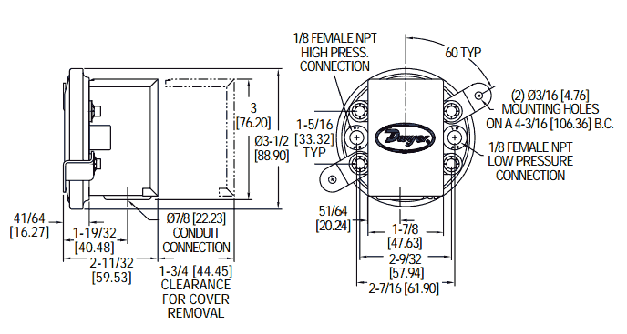
Dwyer 1900 series Low Differential Pressure Switch

How To Wire A Well Pressure Switch Perfect Square D Well

Wiring Sensirion i2C Air Flow Digital Differential

Differential Pressure Transducer, Output 420mA HART

The Ferrari 308 master cylinder