Atv12h075m2 Wiring Diagram

Atv12h075m2 wiring diagram. Nve41289 09/2016 9 about the book at a glance document scope the purpose of this document is: Sheet steel grounded casing not supplied with the drive, to be mounted as indicated on the diagram. X gambar 4.1 wiring inverter terhadap plc dan output. Configure the drive page 31 v apply input power to the drive but do not give a.
Access to the terminals if you use stripped wire cables; A1 drive km1 contactor (only if a control circuit is needed) p1 2.2 k reference potentiometer. Pa and pc terminals, to the braking module dc bus 4. Same day shipping most orders.
Shielded cable for connecting the control/signalling wiring. V set the motor parameters (in conf mode) only. 20 access to the power terminals. V connect the control part.
17 risk of drive destruction; 26 bbv28581 04/2009 wiring installation diagram (example) 1. 20 access to the power terminals. V set the motor parameters in conf mode only.
Pa and pc terminals, to the braking module dc bus. 17 risk of drive destruction; Seymour switches wiring diagram by using the download button or right select selected image then use save image menu. Access to the terminals if you use stripped wire cables;
Configure the drive (page 32) v apply input power to the drive but do not give a run command. Access to the terminals if you use stripped wire cables; 20 access to the power terminals. Inverter, atv12h075m2 1hp, 220v inverter, atv12h075f1 1hp, 110v 1 1 3u2 73050215 73050218 carriage inverter.
The parameter is available in the four data sets the parameter value is set by the setup routine this parameter cannot be written in the operation of the frequency inverter 6. V connect the line supply, after making sure that the power is off. Wire the drive (page14) v connect the motor, ensuring that its connections correspond to the voltage. V set the motor parameters (in conf mode) only.
Pa and pc terminals, to the braking module dc bus 4. Sheet steel grounded casing not supplied with the drive, to be mounted as indicated on the diagram. This can be replaced by a 10 k potentiometer (maximum). Examples of critical control functions are emergency stop and overtravel stop.
Access to the line supply terminals to connect ring terminals. Bbv28581 05/2013 27 wiring installation diagram (example) 1. Wire the drive (page 20) v connect the motor, ensuring that its connections correspond to the voltage. Shielded cable for connecting the control/signalling wiring.
Shielded cable for connecting the control/signalling wiring. This can be replaced by a 10 kω potentiometer (maximum). This can be replaced by a 10 kω potentiometer (maximum). Pa and pc terminals, to the braking module dc bus 4.
Wiring diagram the grounding wire of the inverter must not be grounded together with other large current loads such as soldering machines or large current motors. October 4, 2021 on basic 4 wire trailer wiring diagram. Access to the line supply terminals to connect ring terminals. Atv12h075m2 main range of product altivar 12.
Shielded cable for connecting the control/signalling wiring. To give you mechanical and electrical information related to the altivar320 drive, to show you how to install and wire this drive. Gambar 3.9 wiring diagram kontrol inverter atv12h037m2. This can be replaced by a 10 kω.
Wiring installation diagram (example) 1. Sheet steel grounded casing not supplied with the drive, to be mounted as indicated on the diagram. Access to the line supply terminals to connect ring terminals. Validity note original instructions and information given in this manual have been written in english (before optional
V connect the control part. Yellow and green are for left and right turns and braking. Sheet steel grounded casing not supplied with the drive, to be mounted as indicated on the diagram. Pada deskripsi kerja plant, akan dioperasikan secara otomatis menggunakan kontrol programmable logic cotrol (plc) berbasis supervisory control and data acquisition (scada).
Configure the drive (page 26) v apply input power to the drive, but do not give a run command. 4.2 electrical diagram sensor / limit switch location. • the designer of any wiring diagram must take account of potential control channel failure modes and, for certain critical control functions, incorporate a way of achieving a safe state during and after a channel failure. V connect the control part.
V connect the line supply, after making sure that the power is off.

Shrink Labels Applicator Sleeve labeller equipment with

ATV12H018M3 Variable speed drive ATV12 0.18kW 0.25hp

SIMOR Technology cara integrasikan inverter altivar atv12

ATV1200A47706363 medium voltage variable speed drive

Schneider Electric ATV212HU55N4 ATV212HU55N4
Ilmu Tehnik Kelistrikan Cara mensettiing inverter

Frequenzumrichter 1ph. 0,75kW 230V IP20
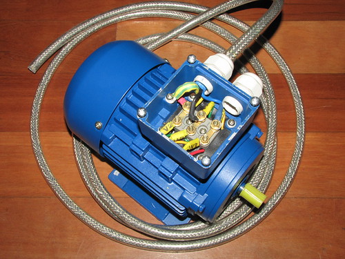
3phase motor with heavyduty shielded cable This will

ATV12PU40M3 Variable speed drive ATV12 4kW 5hp 3ph