240v To 12v Transformer Wiring Diagram
![]()
240v to 12v transformer wiring diagram. Assortment of 12v pool light wiring diagram. In the circuit diagram we can observe that 12v battery. Unless one of the wires has continuity to the transformer core, the polarity doesn't matter. None x4x1 h4 h3h2 h1 x2 x3 primary:
Ac to dc converter circuit diagram with transformer wiring diagram line wiring diagram. Another thing that you will locate a circuit diagram could be traces. Hps imperator tm industrial control transformer wiring diagrams issue date: One set for primary, one set for secondary.
3 as shown in diagram t1 below. Unscrew the cover and you'll see 2 sets of connectors/terminals. Another thing which you will come across a circuit diagram could be lines. Show activity on this post.
The first element is symbol that indicate electrical element in the circuit. The maximum current that can be pulled in this configuration is the total rated by the transformer (i.e. Install 3 or 4 x v 3w led downlights in all rooms. These are the input wires for the transformer, it is connected to the phase and neutral of ac mains.
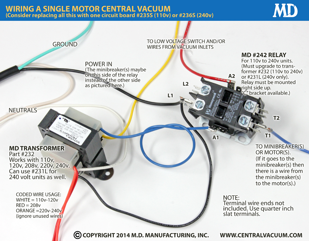
On wiring diagram for 240v led downlights. For v v v or v units. A circuit is generally composed by various components. 5, as shown in diagram t1 below.
My thinking is to get it all installed and wired up, then get a qualified competent and. Rear of transformer with pattress removed. This wire can be combined with either t1 or t3 to get 12v ac across it. You will be capable to learn precisely when the tasks needs to be accomplished, that makes it much easier for you personally to properly control your time.
Connect 230v to terminals marked as primary (at the top of the picture), and the second set of. Single stage with pfc and rectifier wiring diode bridge power acdc transpa background png clipart hiclipart 220 230v 12v 5v regulated convert 220v board mount challenges recom supply steps the powerup circuits what is switching system overview examples. This is another 100 watt inverter circuit diagram. How to make inverter 12v dc to 220v ac making circuit diagram making transformer electr circuit diagram electrical circuit diagram electronics mini projects.
There are just two things which are going to be found in almost any 240 volt single phase wiring diagram. A 120 volts connected to the black red wires provides only 12 volts at the secondary. 50w inverter 12vdc to 220vac. There are the output terminals of the transformer, the voltage across it will be 24v ac.
The following diagram shows the australian plug wiring configuration. A high current mcb supplying storage heaters.sometimes these are run from the main cu, but often from a timeswitch controlled dedicated cu (with either a separate off peak electricity meter, or a dual tariff meter).; This is the centre tapped wire of the transformer. The first component is emblem that indicate electrical component from the circuit.
T1 t1 i) fit the pattress to the wall and connect the 240v ~ 50 hz supply to terminals no.1 and no. A 10 kva transformer volt secondary is to service an 8 kva. 50w inverter 12vdc to 220vac This is the centre tapped wire of the transformer;
If this is the case then the connections have to be in parallel for 120v input and 12v output, or in series for 240v input and 24v output. Can't make it much simpler if using one transformer per downlight, wiring is exactly the same as if the downlights were mains. If you have any questions regarding these wiring diagrams or are having any difficulty correctly installing our transformers, please contact hps customer service or technical support in the u.s. Learn more at schneider el.
A circuit is generally composed by many components. Ii)the cable to the fan must be at least 1.5mm 2 in section and is connected to terminals no. We offer advice on wiring downlights and other lights at dusk lighting. The rated current for each winding added together).
August 28, 2021 on 12v transformer wiring diagram. There are two things that will be found in any 24 volt transformer wiring diagram. A 2x 12v ac transformer became a 1x 12v ac transformer. Transformer windings have a phase relationship, but it's typically not important for power supplies.
/ 12, 2 /2% anfc, 4, 2 1/2% bnfc x4 x1 h10 h2 h3 h1 x2. For instance , when a module will be powered up and it also sends out a new signal of 50 percent the voltage and the technician does not know this, he would think he offers a challenge, as this. The color of the wires may be different. A 24 vac volt alternating current transformer is a step down type of transformer.
October 2007 rev4 page 1 of 9 120 to 24 volt transformer wiring diagram. They also have to be connected in proper phase. This sounds like a transformer with dual input and output windings so that the input can be either 120v or 240v, and the output can be either 12v or 24v.
None x4x1 h4 h3h2 h1 x2 x3 primary.

Wiring Camper Trailer Diagram Trailer Wiring Diagram
![[DIAGRAM] Cl 2 Transformer Wiring Diagram FULL Version HD](https://i2.wp.com/headcontrolsystem.com/wp-content/uploads/2018/08/buck-boost-transformer-208-to-240-wiring-diagram-transformer-wiring-acme-transformer-wiring-diagram-transformer-rh-websitescore-info-acme-buck-boost-transformer-wiring-acme-2d.jpg)
[DIAGRAM] Cl 2 Transformer Wiring Diagram FULL Version HD

Dc Transformer Wiring schematic and wiring diagram

Intermatic control centers and manuals

How To Make 12v DC to 220v AC Converter/Inverter Circuit
240v 24v Transformer Wiring Diagram Class 2 Transformer

480V To 120V Transformer Wiring Diagram Wiring Diagram

240V120V Transformer connection question Parallax Forums

24v Transformer 120 To 24 Volt Wiring Diagram Soffast

Complete Campervan/motorhome electrical conversion wiring

Cool Electronics Circuits 12v to 240v INVERTER
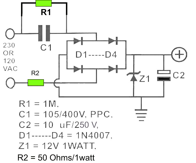
12V DC Power Supply without Transformer Power Supply

Inverter 12V DC to 240V DC Schematic Design

Wiring Manual PDF 120v Transformer Wiring Diagram

How to make inverter 12V to 220V240V 500W (part2) Free

AC 240v to DC 12v converter electrical diagram YouTube

Scematic Diagram 12v To 240v Circuit

12v Transformer Wiring Diagram

What is the simple method to convert a 240v AC to a 12v

50A OEM RV Solar Retrofit Wiring Diagram Outdoors Alley

power supply 230V to 12V step down transformer

240V to 110V Voltage Converter DIY Electronics

24v Transformer Wiring Diagram

12V to 230V Inverter Circuit Diagram using 555 timer IC

How to explain with a diagram the structure and mode of